Isis 3 Application Documentation
mdiscal | Printer Friendly View | TOC | Home |
Calibrates MESSENGER/MIDS EDR/RDR products
| Overview | Parameters | Example 1 |
Description
Messenger images are corrected for the following, in order, during
calibration:
Dark current correction:
Linearity is the measure of how variable is each camera's DN level per unit exposure time and radiance, as a function of variation in exposure time or radiance. Using dark-corrected, desmeared DN values (DCDSI) taken from the center quarter of the images, response linearity was measured with both the NAC and WAC binned and not-binned. Smear Correction: Frame transfer smear corrections for MDIS follow the technique described for NEAR MSI image by Murchie et al. (1999). In brief, an image is exposed for a nominal integration time and is then transferred in 3.84 ms to a memory zone on the CCD, from which the analog signal is digitized line-by-line. Accumulation of signal continues during the finite duration of frame transfer, inducing a streak or frame-transfer smear in the wake of an illuminated object in the field of view, parallel to the direction of frame transfer. Uniformity Correction: Response uniformity, or flat field, is a measure of pixel-to-pixel variations in responsivity. Measurements of response uniformity of the WAC and NAC were conducted in the OCF, at room temperature and while cold, by imaging the integrating sphere with the two 45W bulbs illuminating the interior. Absolute Coefficient Correction: This converts the DN values from responsivity to radiance values. The MODEL dark current option cannot be used if the exposure time exceeds 1 second. In this case, the LINEAR model is selected and a message is issued to the user. Note that there are some extreme cases where an image could not be radiometrically calibrated. When there is more than two factors of binning, FPU or PIXEL, then there are no valid dark pixel colums. For this case, calibrations using STANDARD or LINEAR cannot be used, however, the MODEL can. But, the MODEL cannot be used if the exposure time is exceeds 1 seconds. And in this case, the image cannot be calibrated. When these conditions are detected, a message is issued, but calibration continues using either the MODEL or NONE as the calibration mode. The following is an excerpt from the MESSENGER MDIS calibration document on this process
Raw units are of DN converted to the physical units
of radiance or I/F, following the calibration equation:

L(x,y,f,T,t,b) = Lin[DN(x,y,f,T,t,b,MET) - Dk(x,y,T,t,b,MET) -
Sm(x,y,t,b)] / [Flat(x,y,f,b) * t * Resp(f,b,T)]

where:

L(x,y,f,T,t,b) is radiance in units of W / (m**-2 microns**-1 sr**-1),
measured by the pixel in column x, row y, through filter f, at CCD
temperature T and exposure time t, for binning mode b,

DN(x,y,f,T,t,b,MET) is the raw DN measured by the pixel in column x, row
y, through filter f, at CCD temperature T and exposure time t, for binning
mode b, and Mission Elapsed Time (MET),

Dk(x,y,T,t,b,MET) is the dark level in a given pixel, derived from
a model based on exposure time and CCD temperature,

Sm(x,y,t,b) is the scene-dependent frame transfer smear for the pixel,

Lin is a function that corrects small nonlinearity of detector response,

Flat(x,y,f,b) is the non-uniformity or 'flat-field' correction,

Resp(f,b,T) is the responsivity, relating dark-, flat-, and
smear-corrected DN per unit exposure time to radiance,

and

t is the exposure time in milliseconds.

The above equation assumes that data are in the native 12-bit format in
which they were read off the CCD, and that onboard application of 12-to-8
bit lookup tables (LUTs) has been inverted.

This correction is done step-wise using the calibration tables and
images in this directory as follows:

(1) Inversion of 12 to 8 bit Compression
========================================

8-to-12 bit inversion of DN values is required when the value of
MESS:COMP12_8 is 1 (when the data are 8-bit). There are 8 inverse lookup
tables (LUTs). The table to use is indicated by the value of MESS:COMP_ALG
from 0 through 7. An 8-bit value (in a row of the table) is inverted by
replacing it with the 12-bit value in the column corresponding to a
particular LUT.

The inversion tables are given in the product MDISLUTINV_0.


(2) Subtraction of modeled dark level
=====================================

There are four separate models of dark level (dark current plus
electronics bias), for the MDIS-WAC and MDIS-NAC (as indicated by the
keyword INSTRUMENT_ID), and for each camera, without pixel binning turned
on (MESS:FPU_BIN = 0) or with pixel binning turned on (MESS:FPU_BIN = 1).
The models estimates the dark level Dk(x,y,t,T) as a function of column
position x, row position y, exposure time t (as indicated by the keyword
MESS:EXPOSURE or EXPOSURE_DURATION), and CCD temperature T (as indicated
by the keyword MESS:CCD_TEMP):

Dk(x,y,t,T) = C(T) + D(T) + [E(T) + F(T) * t] * y + {O(T) + P(T) * t +
 [Q(T) + S(T) * t] * y} * x

Variables C(T), D(T), E(T), F(T), O(T), P(T), Q(T), and S(T) are all
third-order functions of CCD temperature, for example:

C(T) = H0 + H1 * T + H2 * T**2 + H3 * T**3

In all cases x or y is in the range 0-1023 for a not-binned image (as
indicated by the keyword MESS:FPU_BIN = 0) or 0-511 for a binned image (as
indicated by the keyword MESS:FPU_BIN = 1). t is in units of milliseconds,
and T is in UNCALIBRATED raw counts of CCD temperature.

For each pixel in column x and row y of an image, application of the
correction is:

DN_dark(x,y,t,T) = DN(x,y,t,T) - Dk(x,y,t,T)

where

DN(x,y,t,T) is DN in 12-bit format,

Dk(x,y,t,T) is the predicted DN level from the dark modeldark model, and

DN_dark(x,y,t,T) is dark-corrected DN.

The eight sets of coefficients for the WAC not-binned, WAC binned, NAC
not-binned, and NAC binned dark models are given in the products
MDISWAC_NOTBIN_DARKMODEL_0, MDISWAC_BINNED_DARKMODEL_0,
MDISNAC_NOTBIN_DARKMODEL_0, and MDISNAC_BINNED_DARKMODEL_0 respectively.


(3) Frame Transfer Smear Correction
===================================

Accumulation of signal continues during the finite duration
of frame transfer induces a streak or frame-transfer smear in the wake
of an illuminated object in the field of view, parallel to the direction
of frame transfer. This smear is approximated as:

Sm(x,y,t,b,f) = SUMM(1,y-1) { t2/t * [DN_dark(x,y,t,b) -
Sm(x,y,t,b,f)] / Flat(x,y,b,f)}

where

Sm(x,y,t,b,f) is the smear in column x and row y at exposure time t
in binning mode b and filter f,

Dk_dark (x,y,t,b) is dark-corrected DN in column x and row y at
exposure time t and temperature T in binning mode b,

Flat(x,y,b,f) is the flat-field correction in column x and row y in
binning mode b and filter f,

t is exposure time in ms, and

t2 is the time for frame transfer (about 3.4 ms) divided by the number of
lines in the image in the direction of frame transfer, 1024 for
full-frame images (when MESS:FPU_BIN = 0) or 512 for binned images (when
MESS:FPU_BIN = 1).

For each pixel in column x and row y of an image, application of the
correction is :

DN_dark_smear(x,y,t,b,f) = DN_dark(x,y,t,b,f) - Sm(x,y,t,b,f)

where

DN_dark_smear(x,y,t,b,f) is dark- and smear- corrected DN,

DN_dark(x,y,t,b,f) is dark-corrected DN, and

Sm(x,y,t,b,f) is the smear calculated as shown above.


(4) Correction for CCD non-linearity
====================================

To remove effects of nonlinearity in WAC image data, the following
corrections should be applied after correction of dark current, bias,
and smear.

For DN_dark_smear > 1
 DN_lin = DN_dark_smear/[0.008760 * Ln(DN_dark_smear) + 0.936321]

For DN_dark_smear <= 1
 DN_lin = DN_dark_smear/0.936321

To remove effects of nonlinearity in NAC image data, the following
procedure should be applied after correction of dark current, bias,
and smear.

For DN_dark_smear > 1
 DN_lin = DN_dark_smear/[0.011844 * Ln(DN_dark_smear) +
0.912031]

For DN_dark_smear <= 1
 DN_lin = DN_dark_smear/0.912031

where

DN_dark_smear is the input dark- and smear-corrected DN, and

DN_lin is linearized dark- and smear-corrected DN.


(5) Flat-field correction
=========================

The flat field correction removes pixel to pixel differences in detector
responsivity, so that the responsivity coefficients can be expressed as
scalars for each filter. There is a separate flat-field image for MDIS-WAC
and MDIS-NAC (as indicated by the keyword INSTRUMENT_ID), without pixel
binning turned on (MESS:FPU_BIN = 0) or with pixel binning turned on
(MESS:FPU_BIN = 1), for each separate filter (as indicated by the keyword
FILTER_NUMBER). All of the files are in the 'FLAT' directory.

For each pixel in column x and row y of an image, application of the
correction is

DN_flat(x,y,f,b) = DN_lin(x,y,f,b) / Flat(x,y,f,b)

where

DN_flat(x,y,f,b) is flat-fielded, linearized, dark- and smear-corrected
DN,

DN_lin(x,y,f,b) is linearized dark- and smear-corrected DN, and

Flat(x,y,f,b) is the value in the appropriate flat-field image.


(6) Conversion from DNs to radiance
 ===================================
The value that relates corrected DN's measured per unit time to radianceis the
responsivity. Responsivity is modeled as a function of which camera is being
used (MDIS-WAC or MDIS-NAC as indicated by the keyword INSTRUMENT_ID), its
binning state (as indicated by the keyword MESS:FPU_BIN), and in the case of the
WAC the filter number (as indicated by the keyword FILTER_NUMBER). The
coefficients used to calculate the responsivity are in the 'RESPONSIVITY'
directory. For a camera, binning state, and filter, the responsivity is
calculated from uncalibrated CCD temperature (as indicated by the keyword
MESS:CCD_TEMP) as follows:

Resp(T,b) = R(t=-30.3C,b) * [correction_offset(b) + T(CCD) * correction_coef1(b)
+ T(CCD)^2 * correction_coef2(b)]

where

Resp(T,b) is responsivity at CCD temperature T in binning state b,

T(CCD) is raw CCD temperature in units of DNs,

R(t=-30.3C,b) is responsivity in binning state b at CCD temperature of 1060 DN
(-30.3C),

correction_offset(b) is the camera-dependent temperature correction offset for
binning state b,

correction_coef1(b) is the camera-dependent temperature correction first-order
coefficient for binning state b.

correction_coef2(b) is the camera-dependent temperature correction second-order
coefficient for binning state b.

The temperature correction defaults to unity at CCD temperature of 1060 DN
(-30.3C).

To apply responsivity to obtain radiance L, the expression is

L = DN_flat / (t * Resp(T,b))

where

L is radiance in units of W / (m**2 microns**1 sr**1),

DN_flat is dark-, smear-, linearity-, and flat field-corrected DN,

t is the exposure time in milliseconds, and

Resp(f,T,b) is the responsivity in filter f at CCD temperature T and
binning state b.


(7) Conversion from radiance to I/F
===================================

To convert from radiance to I/F (also known as radiance factor, the ratio
of measured radiance to that which would be measured from a white
perfectly Lambertian surface), the following expression should be applied:

I_over_F(f) = L(f) * pi * (SOLAR_DISTANCE/149597870.691)**2 / F(f)

where

L(f) is calibrated radiance calculated as described above for some filter
f,

SOLAR_DISTANCE is that value for distance of the target object from the
center of the sun in kilometers (as indicated by the keyword
SOLAR_DISTANCE)

149597870.691 is the number of kilometers in 1 AU

F(f) is effective average solar irradiance sampled under the filter
bandpass.

The effective average solar radiance for each camera and bandpass is given
in the SOLAR directory.
Additional corrective measures have been added to address a contamination event that occurred with the instruments on May 24, 2011 through January 3, 2012 after Mercury orbital insertion. The event and subsequent bake-off has been modeled as additional multiplicative component to the output values. CategoriesRelated Objects and DocumentsApplicationsHistory
|
Parameter GroupsFiles
Options
|
Files: FROM
Description
This is the Isis Cube to be calibrated.
| Type | cube |
|---|---|
| File Mode | input |
| Filter | *.cub |
Files: TO
Description
This is the output file. The output cube will be a calibrated version of the input cube.
| Type | cube |
|---|---|
| File Mode | output |
| Filter | *.cub |
Options: DARKCURRENT
Description
| Type | string | |||||||||||||||
|---|---|---|---|---|---|---|---|---|---|---|---|---|---|---|---|---|
| Default | MODEL | |||||||||||||||
| Option List: |
|
Options: KEEPDARK
Description
If this is selected, the dark current data is NULLed in the output image. Binning affects the number of columns that are determined to be NULLed as well. Thus, KEEPDARK is overloaded in terms of any columns that contain artifacts that are generated by binning (or wavelet compression) are NULLed as well.
If no binning is applied, then four columns are set to NULL. If any combination of DPU or MP (essentially on-board processing) binning is applied, three columns will be set to NULL. When DPU and MP 2x2 binning occurs (essentially a 4x4 summing) three columns will be NULLed. All other combinations of binning will have one column set to the NULL pixel value.
If KEEPDARK = TRUE, then no columns are NULLed on output.
| Type | boolean |
|---|---|
| Default | false |
Options: FLATFIELD
Description
This parameter is provided to allow the user to selectively apply the flatfield correction. This parameter can be used in conjuction with DARKCURRENT and RADIOMETRIC to produce additional output products such as DNs (all parameters DARKCURRENT=MODEL and RADIOMETRIC=FALSE).
| Type | boolean |
|---|---|
| Default | True |
Options: RADIOMETRIC
Description
This parameter is provided to allow the user to selectively apply the radiometric correction. This parameter can be used in conjuction with DARKCURRENT and FLATFIELD to produce additional output products such as DNs (all parameters DARKCURRENT=MODEL and FLATFIELD=FALSE).
| Type | boolean |
|---|---|
| Default | True |
Options: IOF
Description
This option, when set, will convert the output to I/F from radiance values. To convert from radiance to I/F (also known as radiance factor, the ratio of measured radiance to that which would be measured from a white perfectly Lambertian surface), the following expression should is applied:
I_over_F(f) = L(f) * PI * (SOLAR_DISTANCE/149597870.691)**2 / F(f)
where L(f) is calibrated radiance calculated for some filter f,
SOLAR_DISTANCE is that value for distance of the target object from
the center of the sun in kilometers (as indicated by the keyword
SOLAR_DISTANCE), 149597870.691 is the number of kilometers in 1 AU
and F(f) is effective average solar irradiance sampled under the
filter bandpass.
If the observed target is not of a valid body as recognized by NAIF, the output is left in radiance.
| Type | boolean |
|---|---|
| Default | True |
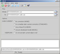
Example 1Calibrating an MDIS image Description
This example will show the calibration process of a MDIS image
Command Line
mdiscal FROM=EW0089565626A.cub
TO=EW0089565626A.calib.cub DARKCURRENT=MODEL
Calibration process of a MDIS image, using the MODEL dark
current option
GUI Screenshot
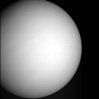
Input Image
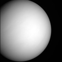
Output Image
|