This program projects an ISIS level0 or level1cube to a map (ISIS level2 cube).
The input cube requires SPICE data and therefore the program spiceinit should be run on it
prior to cam2map. The map projection is defined using a
PVL file specified with the MAP parameter. The system default is to use the Sinusoidal projection
($ISIS3DATA/base/templates/maps/sinusoidal.map). To learn more about using map projections in ISIS,
refer to the ISIS Workshop
"Learning About Map Projections".
If you need to generate your own map file you can use the maptemplate program or alternatively,
hand create a file using your favorite editor. The file need only specify the ProjectionName
as defaults will be computed for the remaining map file parameters. The following table indicates
how the defaults are established:
PARAMETER
DEFAULT
TargetName
Read from Instrument group in the input cube labels
Computed from the input cube or read from the map file. However, any combination of the
four values can then be overridden by the user. The values the user specifies are expected
to be in the coodinate system of the projection.
Computed from the input cube or read from the map file. The value can be overridden by the user.
If you only entered the input cube (FROM) and output cube (TO) and changed no other parameters the
following is the default Mapping group:
  Group = Mapping
    TargetName             = Obtained from the Instrument group
    EquatorialRadius       = Obtained from TargetAttitudeShape kernel
    PolarRadius            = Obtained from TargetAttitudeShape kernel

    LatitudeType           = Planetocentric
    LongitudeDirection     = PositiveEast
    LongitudeDomain        = 360 (Could be automatically adjusted to 180 by LONSEAM)

    MinimumLatitude        = Computed from the input camera cube
    MaximumLatitude        = Computed from the input camera cube
    MinimumLongitude       = Computed from the input camera cube
    MaximumLongitude       = Computed from the input camera cube

    ProjectionName         = Sinusoidal
    CenterLongitude        = Average of MinimumLongitude and MaximumLongitude
    PixelResolution        = Computed from the input camera cube
  EndGroup
The map file can be an existing map projected (level2) cube. A level2 cube has PVL labels
and contains the Mapping group. Depending on the values of the input parameters, the output
cube can use some or all of the keyword values of the map file. For instance, setting
MATCHMAP = true causes all of the mapping parameters to come from the map file, resulting
in an output cube having the same number of lines and
samples as the map file. If MATCHMAP = true and the map file is missing
a keyword like PixelResolution, the application will fail with a PVL error. Setting
MATCHMAP=false allows for some of the mapping components to be overridden by the user or
computed from the FROM cube.
If you are attempting to construct a mosaic, it is important that the PixelResolution, EquatorialRadius,
PolarRadius, LatitudeType, LongitudeDirection, LongitudeDomain, ProjectionName, and projection
specific parameters (e.g., CenterLongitude, CenterLatitude) are the same for all cubes. That is,
you should create one map file and use it as input for all the cubes in your mosaic. By letting the
minimum and maximum latitude and longitude values default, the application will determine the coverage of each image.
However, if the mosaic Latiude and Longitude range is entered, each output image will be projected to the full
size of the mosaic resulting in large file sizes and images with many NULL pixels.
The following Mapping group could be used for mosaicking:
Finally, depending on the projection, problems can occur with cubes that fall on the projection
longitude seam. For example, if you are making a mosaic with LongitudeDomain = 360 and your
cube crosses 0/360 seam, this program would compute the default longitude range of the cube to
MinimumLongitude = 0 and MaximumLongitude = 360. A very large output image could be created
depending on the pixel resolution. The LONSEAM parameter allows you to selectively handle this case.
If you are making mosaics near the seam you will need to understand and alter the default for this parameter.
Section 14 of The ISIS Workshop "Learning About Map Projections" includes an example to help
illustrate the problem.
This program replaces the following
applications
existing in previous versions of ISIS:
lev1tolev2
plansinu
planorth
History
Kay Edwards
1986-09-02
Original version
Jeff Anderson
2003-05-02
Converted to Isis 3.0
Jeff Anderson
2003-06-05
Added to Camera category
Stuart Sides
2003-07-29
Modified filename parameters to be cube parameters where necessary
Jeff Anderson
2003-12-01
Reworked defaults for user parameters
Jeff Anderson
2004-01-21
Modified resolution parameters to eliminate inclusion/exclusion
dependences.
Jeff Anderson
2004-02-13
Added AUTOLON parameter
Jeff Anderson
2004-02-25
Fixed bug with ground range user option
Elizabeth Miller
2005-10-25
Added appTest
Jacob Danton
2005-12-02
Updated appTest
Elizabeth Miller
2006-03-23
Fixed appTest to reflect changes made in all camera models
Tracie Sucharski
2006-04-04
Check to see if center of input image projects, if it does, force the tile containing center
to be processed in ProcessRubberSheet.
Jeff Anderson
2006-04-04
Reworked user interface
Elizabeth Miller
2006-04-10
Reworked code for new user interface and added helper buttons
Elizabeth Miller
2006-05-18
Depricated CubeProjection and ProjectionManager to ProjectionFactory
Elizabeth Miller
2006-05-30
Moved Helper buttons and fixed error checking in helper methods
Elizabeth Miller
2006-09-06
Modified call to ProjectionFactory CreateForCube method to include a value of false
for the newly added sizeMatch parameter
Jeff Anderson
2006-12-06
Test to see if target is sky and abort
Jeff Anderson
2007-03-13
Add minimize option for DEFAULTRANGE
Steven Lambright
2007-06-22
Fixed typo and corrected XML
Steven Lambright
2007-08-22
Fixed lonseam option to work with minimize option correctly
Stuart Sides
2008-02-11
Fixed bug where the ground range was not pulled from the map file when
it was supposed to be (using DEFAULTRANGE = MAP).
Christopher Austin
2008-04-18
Added the MATCHMAP option.
Steven Lambright
2008-05-12
Removed references to CubeInfo
Christopher Austin
2008-07-15
Changed MATCHMAP to default off
Steven Lambright
2008-08-04
Changed MATCHMAP to have exclusions. If MATCHMAP is true, the PIXRES and DEFAULTRANGE
options can not be set. Changed the code to enforce MATCHMAP.
Steven Lambright
2008-09-10
Added the ability to change ProcessRubberSheet's tiling sizes. Now the Camera will decide upon the
tiling sizes used in ProcessRubberSheet, in order to fix problems found with the push frame cameras which
have small framelet sizes (less than 64 pixels tall). This is a passive ability with respect to the user;
no options or differences should be noticable.
Christopher Austin
2008-10-31
Fixed DEFAULTRANGE > CAMERA option to accept MINLAT, MAXLAT, MINLON, and MAXLON
as overriding values.
Christopher Austin
2009-01-27
Fixed parameter names.
Travis Addair
2009-08-10
Mapping group parameters are now placed into the print file.
Steven Lambright
2011-01-31
Improved documentation
Jai Rideout
2011-02-10
Print file now includes PixelResolution, Scale, UpperLeftCornerX, and UpperLeftCornerY in Mapping group.
Lynn Weller and Debbie A. Cook
2012-01-17
Updated documentation text, added glossary links, and improved compatability with Isis documentation.
Jeff Anderson
2012-04-30
Add forward and reverse patch rubbersheeting parameters.
Debbie A. Cook
2012-07-06
Updated Spice members to be more compliant with Isis coding standards. References #972.
Debbie A. Cook
2012-10-11
Updated to use new Target class. References Mantis ticket number #775 and #1114.
Tracie Sucharski
2012-12-06
Changed to use TProjection instead of Projection. References #775
Kimbelry Oyama
2013-07-11
Removed redundant checks for !ui.GetBoolean("MATCHMAP") from if statements. Added
ui.WasEntered before some of the parameters are used. Disabled LONSEAM when MATCHMAP
is selected. Fixes #1613.
A file containing the desired output mapping parameters in PVL. This
file can be a simple label file, hand produced, or created via
the maptemplate program. It can also be an existing cube or cube label
which contains a Mapping group. In the latter case the FROM cube
will be transformed into the same map projection, resolution, etc.
This forces all of the mapping parameters to come from the
map file. Additionally, when the map file is an image the TO file will have the
same number of lines and samples as the map file.
This parameter is used to specify how the default latitude/longitude ground range for the output map projected image
is obtained. The ground range can be obtained from the camera or map file. Note the user can overide the default
using the MINLAT, MAXLAT, MINLON, MAXLON parameters. The purpose of the ground range is to define the coverage
of the map projected image. Essentially, the ground range and pixel resolution are used to compute the size
(samples and line) of the output image.
Type
string
Default
MINIMIZE
Option List:
Option
Brief
Description
MINIMIZE
Minimize output image size
This option will use the camera and projection in combination to ensure the output image size
(samples, lines) is minimized. Using a ground range can cause NULL padding for projections with
curved merdians and/or parallels and hence large output images. The amount of padding can be
quite large for extremely high resolution maps.
Exclusions
MINLAT
MAXLAT
MINLON
MAXLON
TRIM
Inclusions
LONSEAM
CAMERA
Compute default range from input cube
This option will automatically determine the mininum/maximum latitude/longitude from the input
camera model cube specified using the FROM parameter.
Inclusions
LONSEAM
MAP
Read default range from map file
This option will read the mininum/maximum latitude/longitude from the input map file.
All four values are expected to be defined.
The minimum latitude of the output map. If this is entered by the user it will override
the default camera or map value. By default, planetocentric latitudes are assumed unless
the map file specifies otherwise.
The maximum latitude of the output map. If this is entered by the user it will override
the default camera or map value. By default, planetocentric latitudes are assumed unless
the map file specifies otherwise.
The minimum longitude of the output map. If this is entered by the user it will override
the default camera or map value. By default, positive east longitudes in the range of 0 to
360 are assumed unless the map file specifies otherwise.
The maximum longitude of the output map. If this is entered by the user it will override the
default camera or map value. By default, positive east longitudes in the range of 0 to 360
are assumed unless the map file specifies otherwise.
If this option is selected, pixels outside the latitude/longtiude
range will be trimmed (set to null).
This is useful for certain projections whose lines of latitude and
longitude are not parallel to image lines and sample columns.
With this option you can turn on/off the automatic longitude domain switching that occurs
when a file crosses the boundary of the longitude domain (0-360 or -180 to 180). If
the switching is turn off then you have the choice of making the program continue or
exit when the cube does cross the bounday.
Type
string
Default
AUTO
Option List:
Option
Brief
Description
AUTO
Automatically correct Longitude Domain
If the cube crosses the longitude seam automatically compute the LongitudeDomain.
When the cube is near 0 or 360 degrees the program will assume 180 LongitudeDomain.
When the cube is near 180 or -180 degrees it will assume 360 LongitudeDomain.
ERROR
Abort program if cube crosses seam
If the cube crosses the longitude seam the program will exit with an error message
CONTINUE
Continue program if cube crosses seam
If the cube crosses the longitude seam the program will continue. The LongitudeDomain
in the map file will be used. If the map file does not have a LongitudeDomain, 0-360
will be used. Note that this could create an extremely large image.
Used to choose the warping algorithm, either the forward patch algorithm or the reverse patch
algorithm. The default is to automattcally choose the algorithm based on the input camera type
(e.g., framing, linescan, pushframe).
Type
string
Default
AUTOMATIC
Option List:
Option
Brief
Description
FORWARDPATCH
Forward patch warp algorithm
Patches are uniformly distributed over the input cube (FROM). For each input patch, the lat/lons of
the four corners coordinates are computed using the camera model.
Those four lat/lon coordinates are used by the
map projection to determine four output pixel coordinates. Then the
four output to input image coordinates are fit with two affine transforms.
That is, isamp=f(osamp,oline) and iline=g(osamp,oline)
where f = A+B*osamp+C*oline and similarly for g.
If the estimated input/sample
line (as computed by the affine transform) at the center of the patch is within a tenth
of a pixel of the actual computation using the projection and camera model,
the affine transforms are used to place the calculated input pixels in the output patch
(using the specificed INTERPOLATOR).
Inclusions
PATCHSIZE
REVERSEPATCH
Reverse patch warp algorithm
Patches are uniformly distributed over the output cube (map projected product). For each
output patch, the lat/lons of the four corners coordinates
are computed using the map projection. Those four lat/lon coordinates are used
by the camera model to determine four input pixel coordinates. Then the
four output to input image coordinates are fit with two affine transforms. That is,
isamp=f(osamp,oline) and iline=g(osamp,oline) where f = A+B*osamp+C*oline and similarly for g.
If the estimated input/sample
line (as computed by the affine transform) at the center of the patch is within a
tenth of a pixel of the actual computation using the projection and camera model,
the affine transforms are used to place the calculated input pixels in the output patch
(using the specificed INTERPOLATOR).
Inclusions
PATCHSIZE
AUTOMATIC
Automatically select warp algorithm
The automatic option will choose the appropriate algorithm depending on the camera type
of the input cube (TO). If the cube is a framing camera image,
the reverse algorithm will be used with a PATCHSIZE of 4. If the cube is a line scan image,
the forward algorithm will be used with a PATCHSIZE of 5. If
the cube is a push frame camera (e.g., LRO WAC, MRO MARCI, or THEMIS VIS)
the forward transform with a PATCHSIZE of the pushframe framelet height will be used.
It is recommended
that you always use automatic for push frame cameras to ensure the patch size does not cross
multiple framelets.
The forward and reverse patch algorithms try to fit an affine tranform between the
camera model coordinate and projection coordinate using the four
corners of the patches. Patchs that are too large may run faster at the risk of
missing higher resolution information about the DTM. For example a patch
of 256x256 may have the same elevation at the four corners and center of the grid but a
crater may exist in one of the four quadrants of the patch. The crater,
up to 128 pixels in diamter may not be properly orthorectified. In general, small patch
sizes are recommended (e.g., 4, 8).
This example is the first of two different runs of cam2map
demonstrating the LONSEAM option. In this case it is set to AUTO.
All the user input parameters in this example are identical to the
following example except for LONSEAM and TO. The default for LONSEAM
is AUTO.
This is the command line used to create the output for the AUTO
version of the LONSEAM example.
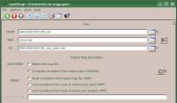
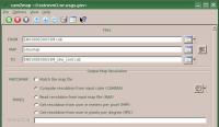
GUI Screenshot
cam2map GUI part 1
Example GUI top of page
Screen shot of top of GUI with parameters filled in for input
files, output file, and output map resolution.
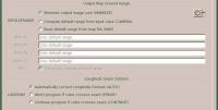
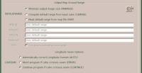
cam2map GUI part 2
Example GUI middle of page
Screen shot of middle of GUI with parameters filled in for the
output map ground range and the longitude seam options. Under
the output map ground range section, notice the grayed out
parameters. These values are computed and not allowed to be
modified when DEFAULTRANGE = MINIMIZE. This is the default.
The LONSEAM option has been set to AUTO in this example.
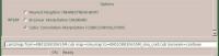
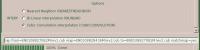
cam2map GUI part 3
Example GUI bottom of page
Screen shot of the bottom of the GUI showing the Options menu.
The default value for INTERP is selected (CUBICCONVOLUTION).
Input map file defining the desired output map projection. This
file is in PVL format.
Output Image
Output of cam2map run with LONSEAM=AUTO
Output image for cam2map LONSEAM=AUTO
Parameter Name:
TO
This is the output of cam2map demonstating LONSEAM set
to AUTO. Contrast this output with the next example
which was created with the LONSEAM set to CONT.
Example 2
Demonstrates the AUTO LONSEAM option
Description
This example is the second of two different runs of cam2map
demonstrating the LONSEAM option. In this case it is set to CONT.
All the user input parameters in this example are identical to the
previous example except for LONSEAM and TO.
This is the command line used to create the output for the CONT
version of the LONSEAM example.
GUI Screenshot
cam2map GUI part 1
Example GUI top of page
Screen shot of top of GUI with parameters filled in for input
files, output file, and output map resolution.
cam2map GUI part 2
Example GUI middle of page
Screen shot of middle of GUI with parameters filled in for the
output map ground range and the longitude seam options. Under
the output map ground range section, notice the grayed out
parameters. These values are computed and not allowed to be
modified when DEFAULTRANGE = MINIMIZE. This is the default.
The LONSEAM option has been set to CONT in this example.
cam2map GUI part 3
Example GUI bottom of page
Screen shot of the bottom of the GUI showing the Options menu.
The default value for INTERP is selected (CUBICCONVOLUTION).
Input map file defining the desired output map projection. This
file is in PVL format.
Output Image
Output of cam2map run with LONSEAM=CONT
Output image for cam2map LONSEAM=CONT
Parameter Name:
TO
This is the output of cam2map demonstating LONSEAM set
to CONT. Contrast this output with the previous example
which was created with the LONSEAM set to AUTO.
Example 3
Demonstrates one of two different ways to use MATCHMAP
Description
This example is the first of two different runs of cam2map
demonstrating usage of MATCHMAP. In both this example and the next,
MATCHMAP is set to YES. In this case MAP is an Isis3 level 2 image.
The mapping parameters of the output file will be read from the
mapping group of the MAP level 2 image.
This is the command line used to create the output for the level 2
image version of the MATCHMAP example.
GUI Screenshot
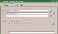
cam2map GUI part 1
Example GUI top of page
Screen shot of top of GUI with parameters filled in for input
files, output file, and output map resolution. Notice that with
MATCHMAP checked the remaining output map resolution parameters
are grayed out to show that they are no longer available for
input. All the mapping parameters will be read from the level 2
image entered for MAP.
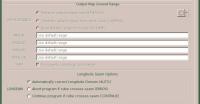
cam2map GUI part 2
Example GUI middle of page
Screen shot of middle of GUI showing parameters for the
output map ground range and the longitude seam options. Under
the output map ground range section, notice all the parameters
are grayed out. These values are all read or computed from the
parameters in the mapping group of the level 2 image entered as
the MAP and not allowed to be modified because MATCHMAP=YES.
The LONSEAM option has been set to AUTO in this example (the
default).
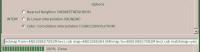
cam2map GUI part 3
Example GUI bottom of page
Screen shot of the bottom of the GUI showing the Options menu.
The default value for INTERP is selected (CUBICCONVOLUTION).
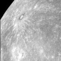
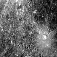
Input Images
Input Messenger image
Input image for MATCHMAP examples
Parameter Name:
FROM
This is a Messenger narrow angle camera image.
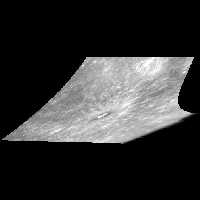
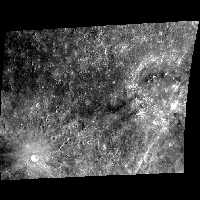
Input level 2 image used for MAP
Input image for MATCHMAP examples
Parameter Name:
MAP
This is a Messenger narrow angle camera image previously projected into an equirectangular map.
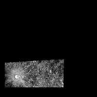
Output Image
Output of cam2map run with MATCHMAP=YES and map file
Output image for cam2map LONSEAM=AUTO
Parameter Name:
TO
This is the output of cam2map demonstating the use of
MATCHMAP=YES with an Isis level 2 image as MAP.
Contrast this output with the level 2 image used as MAP
and with the next example which was also created with
MATCHMAP=YES, but uses an Isis map file as MAP.
Example 4
Demonstrates one of two different ways to use MATCHMAP
Description
This example is the second of two different runs of cam2map
demonstrating usage of MATCHMAP. In both this example and the
previous, MATCHMAP is set to YES. In this case MAP is an
Isis map file. The mapping parameters of the output file will
be read from this map file.
This is the command line used to create the output for the map file
version of the MATCHMAP example.
GUI Screenshot
cam2map GUI part 1
Example GUI top of page
Screen shot of top of GUI with parameters filled in for input
files, output file, and output map resolution. Notice that with
MATCHMAP checked the remaining output map resolution parameters
are grayed out to show that they are no longer available for
input. All the mapping parameters will be read from the map file.
The application will throw an error if any required information
is missing.
cam2map GUI part 2
Example GUI middle of page
Screen shot of middle of GUI showing parameters for the
output map ground range and the longitude seam options. Under
the output map ground range section, notice all the parameters
are grayed out. These values are all read or computed from the map
file values and not allowed to be modified because MATCHMAP=YES.
The LONSEAM option has been set to AUTO in this example (the
default).
cam2map GUI part 3
Example GUI bottom of page
Screen shot of the bottom of the GUI showing the Options menu.
The default value for INTERP is selected (CUBICCONVOLUTION).
Input map file defining the desired output map projection. This
file is in PVL format.
Output Image
Output of cam2map run with MATCHMAP=YES and map file
Output image for cam2map LONSEAM=AUTO
Parameter Name:
TO
This is the output of cam2map demonstating the use of
MATCHMAP=YES with an Isis map file as MAP. Contrast
this output with the previous example, which was also
created with MATCHMAP=YES, but uses an Isis level 2 image
for MAP.