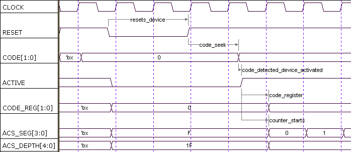
Diagram above shows timing between decoder inputs and internal control signals.
Timing Diagram (VDK7R12)

Diagram
above shows timing between decoder inputs and internal control
signals.
Input signals are :
CLOCK, its frequency is about 16 times DATA_RATE. This condition assumes number of ACS to be four.
RESET, active low, resets device and most registers.
CODE/Symbol, input codes to be decoded at a rate of DATA_RATE
First condition after RESET, device is in not ACTIVE mode. When first code detected at CODE (means CODE has a non-zero value), device is activated (ACTIVE = '1') and on the next CLOCK rising edge event, device counters : ACS_SEG, ACS_DEPTH, control signals : INIT, HOLD, TB_INIT, TB_HOLD, start signalling to the rest of decoder processes.

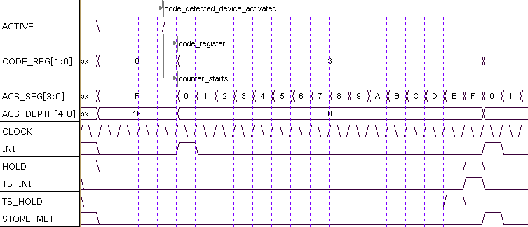
Diagram above shows device condition after ACTIVE.
ACS_SEG is a four bit binary counter with rising edge CLOCK. Its sixteen iteration is used to determine current status of BranchMetric, Add-Compare-Select, Decision, and Trace-back processes. Sixteen iteration comes from the condition of Viterbi Decoder with K=7 which has 64 StateMetrics to be calculated, with four StateMetric each indicating usage of four ACSUs.
INIT signal is raised to initialize DecisionUnit at current ACS_DEPTH.
HOLD signal is raised to clock LowestState storing at LW_ST register.
STORE_MET signal is raised to enable storing all of StateMetrics at MetricRegisterUnit (M_RAM).

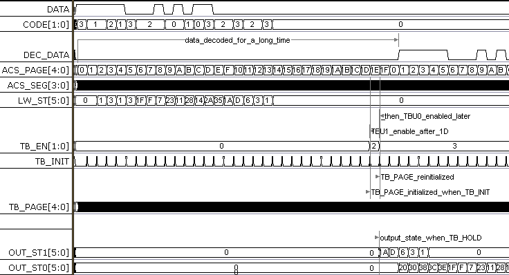
After device starts, input CODEs is processed through all combinational and sequential logic within device. As mentioned in previous section, received CODEs activate the internal ACTIVE signal and then, the ACS_SEG starts counting.
We note here an another important counter that is ACS_PAGE. Consider we use RAM(s) to write the SurvivorData, we need the data to be written and an address of the data location at RAM. Here we see that address is a combination between ACS_PAGE and ACS_SEG. If we move the CodeTrellis into RAM, ACS_PAGE indicates time count while ACS_SEG indicates a block of SurvivorBits with corresponding State.

TB_PAGE and TB_INIT
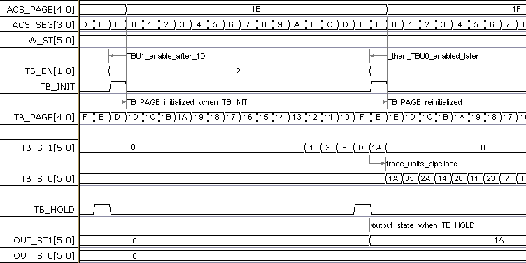
More detailed diagram is shown above. Look at ACS_PAGE, it's value is 1E. At this moment, the TraceBack process is started for the first time after device activated. After ACSU finished writing at page 1D and while it is writing at page 1E, the TraceBackUnit begins reading SurvivorInformations of the last (1D's) page ACSU just written. The binary down-counter TB_PAGE shows current page information TBU accessed. This counter is controlled by TB_INIT and CLOCK signals, and it's initial value is previous ACS_PAGE.
TB_ST, TB_HOLD, and OUT_ST
The LowestState becomes the initial decoding address at page 1D. From diagram above we see that : LW_ST = 'b000000. For initial step, the TraceBackUnit will fetch survivor bit corresponds to this LW_STATE. Next iteration until page 14, the SurvivorBits are zeros. But, we on page 13 until 0F, TraceBackUnit starts receiving ones.
|
TB_PAGE |
TB_ST1 |
SURV_BIT |
|
1D |
= LW_ST = 'b000000 |
0 |
|
.. |
.. |
.. |
|
13 |
'b000000 (0) |
1 |
|
12 |
'b000001 (1) |
1 |
|
11 |
'b000011 (3) |
0 |
|
10 |
'b000110 (6) |
1 |
|
F |
'b001101 (D) |
1 |
|
E |
'b011011 (1A) |
(HOLD) |
Decoder's architecture shows that the decoder use two TraceBackUnits : TBU1 and TBU0. Why do we use two? Its explained in ArchitecturalStrategy. But, it can be simply explained here that each TBU corresponds to one step iteration of ACS_PAGE, furthermore, one CODE. With TraceBackDepth of about 30 and one Survivor decoded each clock, the TBU1 can only process until 15 depth and TBU0 then continues processing until 30's depth in pipelined fashion.
In diagram "TraceBack Signals(1)" is shown that OUT_ST1 and OUT_ST0 are produced by TBU1 and TBU0. TBU1 uses LW_ST as initial decoding state to produce OUT_ST1 and TBU0 uses OUT_ST0 as initial decoding state to produce OUT_ST0. At the end of TraceBack process, the LSB of OUT_ST0 (= incoming SURV_BIT at TBU0) is the DecodedData (DEC_DAT).