| Geometer's Angle no. 9: Perspectiva Geometrica |
|---|
INTRODUCTION
In this issue of the Nexus Network Journal
dedicated to Perspective, I would like to present some drawings
and constructions for those whose interests are in systems of
perspective, and the role that grid making may have played in
the development of perspective in the early Renaissance. The
information presented here may also be of assistance to those
who are interested in learning some techniques for rendering
perspective drawings, although this information assumes some
preliminary knowledge of the elements, rules, and vocabulary
of the science of perspective systems.
I recommend two books on the subject. Principles of Perspective [Walters and Bromham 1974] is a little known work on the subject of perspective. Written for those who wish to draw perspectively, this book offers one of the most accurate, understandable, and concise works on the subject to be found. There is not an abundance of text, and the illustrations are excellent, clear, and exact. Another book, probably known to many of our readers and that I highly recommend, is Architectural Representation and the Perspective Hinge [Perez-Gomez and Pelletier 1977]. Where Principles of Perspective is a precise and practical approach to the methods of perspective drawing, Perspective Hinge is a thoughtful discussion to the subject as it has related to architecture (although it is much more than that), and how perspective techniques used in architectural rendering can be found in the architecture itself, and the various ways the two have been intertwined over the centuries. It is excellent reading.
I have wondered, when developing a grid, [1] whether the same thoughts went through the masters' minds when they were making them; that is, there are aspects of the grid that suggest three-dimensional space, and a sufficiently developed grid contains the illusion of perspective space, complete with vanishing points and horizon lines. I have also considered that it is possible that if I've noticed it, early Renaissance perspectivists must surely have. The question must then be, did they "see" the similarities between certain geometric grids and the potential that these grids have for representing real space so as to make the connection? I was trained in how to do perspective and I learned how to see perspectively through the employment of geometric structures. But what helped painters of the thirteenth and fourteenth centuries to "see" perspectively through the use of geometric structures? In what ways does modern learning of perspective compare, if at all, to the way Giotto's and Duccio's observations were handed on to the Renaissance masters? Did these masters show how perspective space should look in a painting for Renaissance artists to learn from? Did Giotto's use of geometry in rendering architectural settings set the stage for how perspective space could look, and even more importantly: did his paintings and frescos present a situation that perhaps the time had come for artists to begin to see space in a new and more natural way? These issues, then, are central to the development of linear perspective: how did the masters originally come to see specific geometric techniques as tools for the embodiment of "seeing" ideal, mathematical space?
In my own experiences and in discussions with others, notably with my colleague, Richard Talbot [2] (and who has an article in this issue), the idea of geometric grids as possibly generating the 'look' of perspective space and that come as a product of the development of the grid, have been noted and discussed. There are also certain techniques in grid construction that will provide proportioning systems for perspective drawings, as will be seen in my latter examples below. Whether the awareness of these qualities of the grid came first, that is, if geometric grids induced the founding fathers of this "mathematical space" to see in the grid itself a valid representation of space, or if the desire to create an ideal, yet practical, method for recording the illusion of space came first, I just cannot say with absolute certainty. In The Science of Art [1992], Martin Kemp states that perspective--as we think of it today--was the result of intellectual, scientific, and artistic inquiries into the subject of optics and seeing during the Renaissance [Kemp 1992, 1]. Specifically, Professor Kemp gives the credit for the invention of linear perspective to Filippo Brunelleschi in the early 1400s. I agree with this position, and yet I am also interested in Professor Kemp's statement in chapter one regarding "… questions of inexhaustible complexity, not only with respect to the historical circumstances which led to Brunelleschi's invention, but also in relation to the nature of what he actually invented" [Kemp 1992, 9]
It seems that Brunelleschi's experiences with measurements and surveying while in Rome, and his excellent education (which certainly must have included studies of Euclid's Optics, and medieval treatises on the same subject) put him in an ideal situation to conceive of the process of perspective drawing; but even with this in mind, I must also remain open to the possibilities that geometry (and, geometric construction), by its nature, was also a catalyst for this new way of thinking and seeing. Geometry was needed for most of what Filippo was doing. But what were all of the geometric systems he was utilizing and developing? Specifically, I am speaking of the nature of grids as generated from rectangles and the square, and his familiarity with them. Did Filippo create a system of geometry for rendering perspective directly and specifically with the intention of making perspective, or did he advance a technique based on a particular quality of geometric grid making that is present in rectangular armatures? It could be that both happened more or less simultaneously, but unfortunately, we do not now have any writings on the specifics. As an artist and geometer, I believe it is important to look at the process of grid making as possibly a key element in the development advancement of perspective systems.
In order to see an example of this quality of grid development, I first present a procedure for measured perspective, and then a grid that utilizes a geometric progression to create the illusion of depth. I also offer a drawing that I did that uses the square root of phi for the perimeter ratio, and which demonstrates how space is created in various parts of the drawing. In the former, I show a controlled and mathematical approach to rendering perspective objects and spaces; in the latter, I demonstrate the issue of the grid generating the diminution of a planar surface.
A RECTANGULAR PRISM IN MEASURED, TWO-POINT,
PERSPECTIVE
The
first group of drawings, figures 1 through 9, gives a brief demonstration
on "measured perspective" using two vanishing points.
Measured perspective only requires that the actual dimensions
of the objects or spaces be known. This is also true with projective,
or "drop down" (as it is sometimes called in art and
architecture schools) geometry. This gathering of information
is necessary if one is attempting a precise drawing of an object
that actually exists. Herewith, then, are the procedures.
In Figure 1 we begin with a circle, O, and the horizontal diameter. The diameter, AK, will function as the horizon line/eye level for the drawing. In this set up, the two points, A and K, will be the two vanishing points.
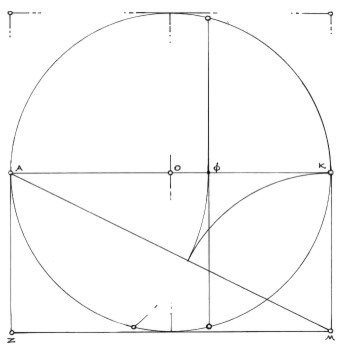
Figure 1
As we are in standard two point perspective, all the verticals will remain parallel, and have their vanishing points at infinity, above and below. In two point perspective, only two of the three dimensions are foreshortened; that is, the lines describing these two dimensions each have their own vanishing point. Hence, we have "two point perspective." The drawing also shows the vertical line, PR. This line represents a vertical plane that cuts through the observer's eye and determines the specific point of intersection on the horizon line where the central visual ray (CVR) is directed. In this drawing, the CVR is labeled, F. In this drawing, I have placed the vertical line, PR, at the golden section of the what?. This is an arbitrary decision, but it also has a direct influence on the position of the object as seen by the observer. This will be addressed in Step 2.
Here, in Figure 2, a classical geometric construction is utilized in the perspective system. It is the Rule of Thales. The rule states that in a semicircle, any point on the semicircle, when connected to the ends of the diameter, will always give a 90° angle. In measured perspective, these two connecting lines to the diameter, AP and KP, are sometimes called Van Pars, which stands for "vanishing parallels." These two lines represent the two dimensions that will be put into perspective, and the ends of the diameter become the two vanishing points that these two dimensions converge to. As the object we are rendering-a rectangular prism- has a 90° corner, the rule works perfectly. The 90° then can move along the vertical line, PR, and into perspective.
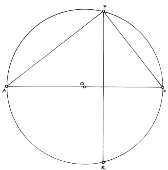
Figure 2
The angles formed at the two vanishing points, A and K, determine the angle that we see the front edge, 90° angle of the object rotated to. Here, the angles are approximately 52° (PKA), and 38° (KAP). Because we are employing the rule of Thales, the two angles will always add up to 90°. Therefore, we can render the object in 30°/60°, or 45°/45°, or even 10°/80°, any combination of angles that add up to 90°. As a result, the front 90° vertical edge will be rotated into those two angles as seen against the picture plane. This is because the van pars become the perspective front edges of the object as they are lifted from the 90° at the Obs. into the perspective space.
In Figure 3, the lines AP and KP have been reflected into the lower half of the circle (still a semicircle), and P has become the point of the Observer. So,
- HL/EL = Horizon Line/Eye Level;
- Obs (SP) = Observer (Station Point);
- CVR = Central Visual Ray;
- CVP = Central Vertical Plane;
- VP1 and VP2 = The two Vanishing Points;
- Van Pars 1 and 2 = The two Vanishing Parallel Lines.
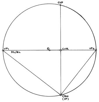
Figure 3
In Figure 4, measuring points have been added.[3] Measuring points are used in the determination of precise foreshortened measurements and are in conjunction with a calibrated scale of measurements. They are always generated by placing the compass point into a vanishing point and opening the lead to the observer. Then this measurement-the van par-is rotated onto the horizon line. So,
Additionally, a base line (BL) and a height line (HL) have been introduced so that a scale of units can be used to determine sizes and lengths in the drawing. This scale is to be determined by the artist for the job at hand, and the units can represent any magnitude. As mentioned, the heights will not be foreshortened, but will only diminish by reduction of size. The crossing of BL and HL is indicated as "0", and the units to the left and right will correspond to those two directions of foreshortened lines; to the left, VP1, and to the right, VP2. The base line can be placed anywhere, and it will determine, at "0", where the front, lower corner and base of the rendered object will be.
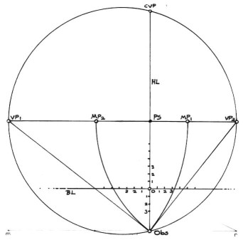
Figure 4
Figure 5 shows a square of 4 units drawn beneath the base line. This has been done in order to construct a golden section rectangle to be drawn in perspective. Any plan may be measured or drawn using the units chosen by the artist. (Here, as the golden section length would not fall conveniently and neatly on a base line measurement, the construction method was used.) The measurements from the base line and the construction can now be transferred onto the orthogonal lines.
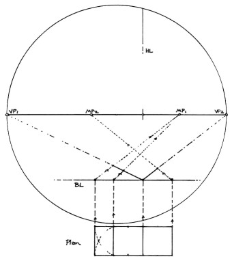
Figure 5
Four units are measured to the left, and a straight edge is then used to the measure point to transfer these four units onto the orthogonal going to VP1 at q1. Next, the same procedure is applied to the right, and the straight edge is then drawn to MP2. These four units are marked on the orthogonal going to VP2 at q2. Lastly, the golden section measurement, F, is drawn onto the orthogonal to VP1 at q3. Now, the front half of the rectangle in perspective plan is drawn to the VPs and the back half can now be added, as seen in Figure 6.
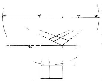
Figure 6
The drawing shows the golden section rectangle, drawn in plan in Figure 5, now in two point perspective.
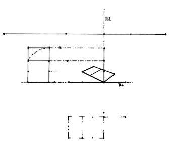
Figure 7
In figure 7, an elevation of a golden section rectangle is drawn on the base line, and its heights are then transferred over to the height line, and the square is four units in height. A golden section rectangle has been drawn for the height of the prism. Measurements of height can be moved around by drawing orthogonals from the top and bottom of all the vertical measurements to the appropriate VPs. This is how the other three vertical edges of the prism were made in Figure 8.
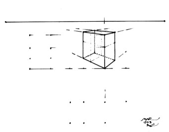
Figure 8
The rectangular prism with guide lines:
Figure 9
The finished perspective drawing of the rectangular prism:
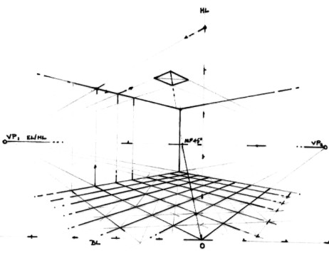
Figure 10
I am including an interior space to demonstrate that measured perspective can also render space. The height line, base line, and the two vanishing points work in concert to move dimensions through the perspective space. Note the 45° measure point for the diagonals of the square grid. As units of magnitude, these squares can be scaled to any size. For example, in this drawing, if we assign a size of three feet to be equal to one square, our eye level is two units from the ground, or six feet (the height of the eye level/horizon line from the base line, 0), then we are then looking at the back walls as being about 21 feet back, and the ceiling 15 feet in height.
THE GRID WITHIN THE GOLDEN SECTION RECTANGLE
In the next series,
figures 11 through 13, I present a grid within the golden section
rectangle that creates a lovely progression demonstrating diminution.
(The phi rectangle was the ratio I originally used when I made
this discovery. The grid becomes a perspective space, with the
diminution starting at the bottom of the rectangle and proceeding
to the top. The top of the rectangle acts as the horizon line.
This technique can be employed in any rectangle, but the results
can vary greatly.[4]
This particular progression is based on the square root of phi
within the phi ratio, as noted on the right.
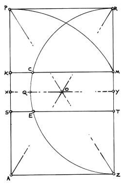
Figure 11
In Figure 11, we have golden section rectangle, APRZ. The rectangle contains two squares, AKMZ and SPRT. O is the center of the rectangle. XY is the horizontal midline of the rectangle. ZQR is a semicircle, with center, Y, and radius, ZY. ZY = YQ = YR.
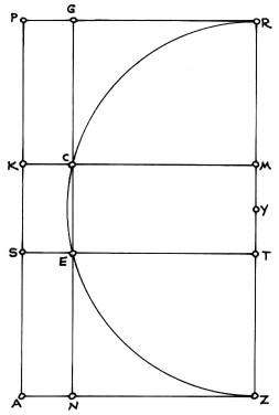
Figure 12
Figure 12 shows the vertical line, NG, generated by the intersections of the semicircle, ZQR, with the sides, KM and ST, of the squares AKMZ and SPRT, at points E and C. This vertical line becomes the key instrument in the creation of the progression.
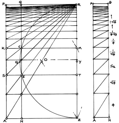
Figure 13
The procedure is as follows:
- Draw the horizontal line, JH, where the diagonal, AR, intersects GN at F, through F.
- Draw the line, JR, from the generated point, J.
- Draw the horizontal line, ST, where JR intersects NG, at point, E, through E.
- Draw the line, SR, from the generated point, S.
- Continue this same procedure up the rectangle toward the top of the rectangle, PR, creating the horizontal lines, LY. KM, UV, WX, etc.
The very tall rectangle on the right side of the illustration, APGN, has been taken from the master rectangle, APRZ. It has been isolated so that the diminution of spaces can be clearly seen, and also so that each horizontal band becomes just a rectangle. The first rectangle at the bottom, labeled, is a phi rectangle. The next one above it, labeled, is a square root of phi rectangle. The next is a square, and so on. Each rectangle, from bottom to top, decreases by the square root of phi, or, divided by 1.272…
THE GRID WITH THE SQUARE ROOT OF PHI RECTANGLE
A variation of
the above techniques involves the square root of phi rectangle.
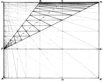
Figure 14
Starting with square root of phi rectangle, AKMZ, horizontal line, PG, is drawn at a golden section of the height, so that PK/AP = AK/PK = F/1. Points C and R are the golden sections of the width. Here any and all of the lines, PG, PR, and PM (and although there are more) act as line NG did in the last construction. In this construction, I particularly like the rectangular shapes within the triangle, PRM. Near P, the shape appears to be square, but as it proceeds to the top of the rectangle, KM, which is the horizon line/eye level here, the shape is distorted into longer, and larger, rectangles, until, at PM, only the nearest edge of the last rectangle can be seen, converging with the horizon line, KM!
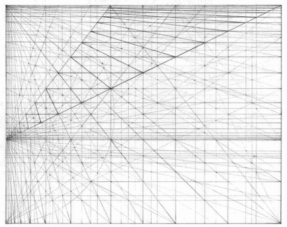
Figure 15
Figure 15 is a graphite drawing of the dense grid developed using this technique. In this drawing, one can see diminution occurring in several places, including at the top, to the far left, and at the horizontal golden section of the rectangle.
CONCLUSION
I hope that these demonstrations motivate
some of you to try drawing with these techniques. Perhaps even
more, I hope that they may provide a point of discussion on the
issue of the nature of geometric grids in creating perspective
space as a natural consequence of the geometric armature. Although
we may never be certain which approach came first-the conscious
decision to develop a working system of geometry to help explain
the way we see, and therefore understand, the world, or the awareness
of the ability of geometry to naturally demonstrate some of the
ways in which we see-perhaps the drawings will keep both possibilities
open whenever discussions about the history of perspective and
geometric systems arise.
Have a peaceful Spring by doing something for peace.
NOTES
[1]
The reader who may be interested in the elements of rectangular
grids might wish to see the Geometer's Angle, No. 2 and no. 3
in the NNJ. return to text
[2] Richard is a very intelligent and gifted artist. I would encourage anyone interested in seeing some amazing and beautiful perspective drawings to look at his work. (Please note that these drawings are done by hand, not computer.) Richard convincingly shows that there can always be a new approach to an ancient method with exquisite and aesthetically pleasing results. Some of us may have come to believe that much about perspective rendering is sterile and mechanical, but Mr. Talbot has taken the art to a new, refreshing, and welcome level; and, his drawings are drawn freehand. return to text
[3] See [Walters and Bromham 1976] for the geometric proof of why the measure points work. return to text
[4] The reader is referred to the Nexus Journal/Geometer's Angle column, Volume 3, Number 4, where the subject of progressions and perspective are addressed. return to text
BIBLIOGRAPHY
Euclid.
The Arabic Version of Euclid's Optics: Edited and Translated
with Historical Introduction and Commentary. Elaheh Kheirandish,
trans. Berlin: Springer-Verlag, 1998. To
order from Amazon.com, click
here.
Alberto Perez-Gomez and Louise Pelletier, Architectural Representation and the Perspective Hinge. Cambridge MA: MIT Press,1997.
Nigel V. Walters and John Bromham, Principles of Perspective. New York: Watson-Guptil, 1976. To order from Amazon.com, click here.
Martin Kemp, The Science of Art. New Haven CT: Yale
University Press, 1992). To order from
Amazon.com, click
here.
|
Mark A. Reynolds, "Perspectiva Geometrica", Nexus Network Journal, vol. 5 no. 1(Spring 2003), http://www.nexusjournal.com/GA-v5n1.html |

Copyright ©2003 Kim Williams Books